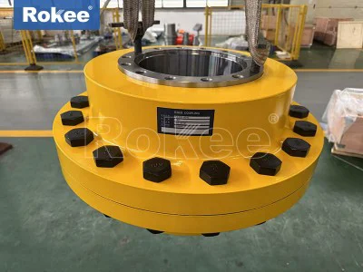
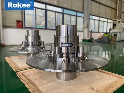
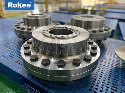
Fork Couplings
Fork coupling is a special mechanical transmission component mainly used to connect two shafts to rotate together to transmit torque, while allowing for a certain degree of axial, radial, and angular displacement. This type of coupling is named after its unique "fork" structural design and plays an important role in modern mechanical transmission systems.
The fork coupling achieves power transmission and deviation compensation through its unique elastic elements and fork structure. When the driving shaft rotates, torque is transmitted to the elastic element through the shift fork, and then power is transmitted to the driven shaft through the elastic element. During this process, the elastic body inside the coupling can absorb and buffer impact loads, while compensating for misalignment issues caused by installation errors, thermal expansion, or foundation settlement.
Compared with ordinary couplings, the prominent features of fork couplings are their three-dimensional compensation capability and vibration damping characteristics. The fork structure allows the coupling to maintain high torque transmission efficiency while experiencing significant axial displacement, making it particularly suitable for situations where frequent axial movement is required.
The structure design of the fork coupling is exquisite, mainly composed of the following key components:
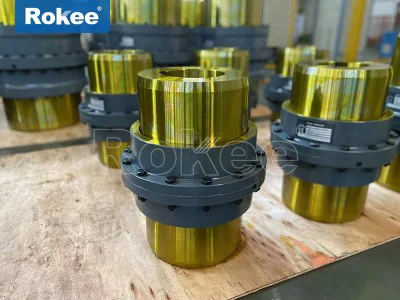
Fork component: usually forged from high-strength alloy steel, precision machined and heat-treated, with two symmetrically distributed fork arms shaped like a tuning fork. The end of the fork arm is designed with a special contour for fixing elastic elements.
Elastic element: Made of polyurethane, rubber or other polymer composite materials, it has excellent elastic properties and wear resistance. Elastic components not only transmit torque but also absorb vibration, and their hardness can be selected between Shore A 60-95 degrees according to application requirements.
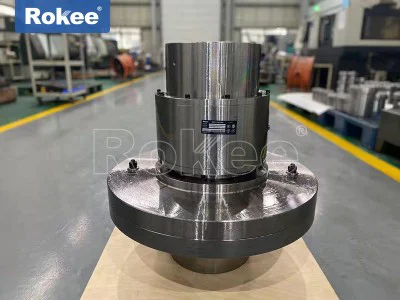
Wheel hub assembly: consists of two metal wheels, connected to the drive shaft and the driven shaft respectively. The wheel hub is usually fixed to the shaft with a cone sleeve or keyway to ensure that it does not slip when transmitting high torque.
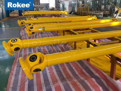
Intermediate connector: In some designs, the fork coupling also includes an intermediate shaft or connecting flange to increase compensation capacity or accommodate special installation requirements.
The latest generation of fork couplings adopts a modular design, with bolt free connection technology between the fork and the elastic element, which is fixed through precision press fitting to avoid stress concentration problems that may be caused by traditional bolt connections. Some high-end products also integrate a status monitoring interface, which can monitor the torque, temperature and other operating parameters of the coupling in real time.
Compared with gear couplings, fork couplings do not require lubrication and are easy to maintain; Compared with diaphragm couplings, it has greater axial compensation capability; Compared with universal couplings, its transmission efficiency is higher (up to 98% -99.5%) and there is no gap.
According to specific application requirements, fork couplings have developed various variant designs:
Standard fork coupling:
Adopting a symmetrical fork structure
Suitable for general industrial transmission
High cost-effectiveness and the widest range of applicationsHigh elasticity fork coupling:
Using specially formulated elastomers
Has extremely high damping characteristics
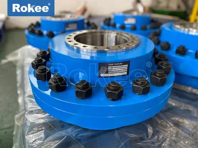
Used in high impact load scenarios such as crushers and compressorsFlange type fork coupling:
Both ends are connected by flanges
Easy to install and disassemble
Suitable for high-power transmission systemsHigh temperature resistant fork coupling:
Using silicone rubber or fluororubber elastomer
Used in high-temperature environments such as metallurgy and chemical industryAnti corrosion fork coupling:
Special surface treatment or use of stainless steel material
Suitable for corrosive environments such as marine and chemical industries
The correct selection is the key to ensuring the reliable operation of the fork coupling, and the following factors need to be considered comprehensively:
Torque demand:
Calculate normal working torque and peak torque
Consider starting torque and braking torque
Choose a model with a rated torque that is 1.5-2 times the actual requiredSpeed matching:
Confirm that the working speed is within the allowable range of the coupling
High speed applications require the selection of models that have undergone dynamic balancingDeviation compensation requirements:
Measure the estimated axial, radial, and angular deviations
Ensure that the coupling compensation capability meets the requirementsEnvironmental conditions:
temperature range
Are there any oil stains, chemicals, or dust present
Outdoor applications need to consider UV protection requirementsSpace limitations:
Measure available installation space
Consider the space required for disassembly and maintenance
Suggested selection steps:
Determine the application type and operating conditions
Calculate the required torque to be transmitted
Evaluate the deviation of the shaft system
Consider environmental factors
Refer to the manufacturer's selection manual or use selection software
Consult professional technical support when necessary
Installation steps:
Check the matching of shaft end dimensions, keyway, and coupling aperture
Clean the contact surface between the shaft and coupling, remove burrs and oil stains
Install the wheel hub using appropriate methods (such as hot installation or hydraulic tools) to avoid hammering
Preliminarily align the two axes and reserve appropriate deviation margin
Install elastic components to ensure symmetry and uniformity
Use a laser alignment instrument for precise alignment (recommended deviation ≤ 0.05mm)
Tighten all fasteners and use anti loosening measures
Fork couplings are widely used in many industrial fields due to their excellent performance:
Pump equipment:
Centrifugal pump, plunger pump, vacuum pump
Effectively absorb the axial pulsation of the pumpFan system:
Centrifugal fan, axial flow fan
Compensate for deviations caused by thermal expansionCompressor:
Screw compressor, piston compressor
Buffer start impact and pulsating torqueConstruction Machinery:
Excavator, loader
Adapt to shaft deformation under harsh working conditionsPower generation equipment:
Diesel generator set, gas turbine
Ensure smooth and reliable power transmissionShip propulsion:
Main shaft and gearbox connection
Compensate for deviations caused by hull deformationSteel metallurgy:
Rolling mill, straightening machine
High temperature resistance and impact resistance