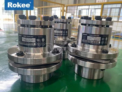
Flexible Membrane Couplings
As a key component in modern industrial transmission systems, flexible membrane couplings have become an ideal choice to replace traditional toothed couplings due to their unique metal elastic element design and excellent performance.
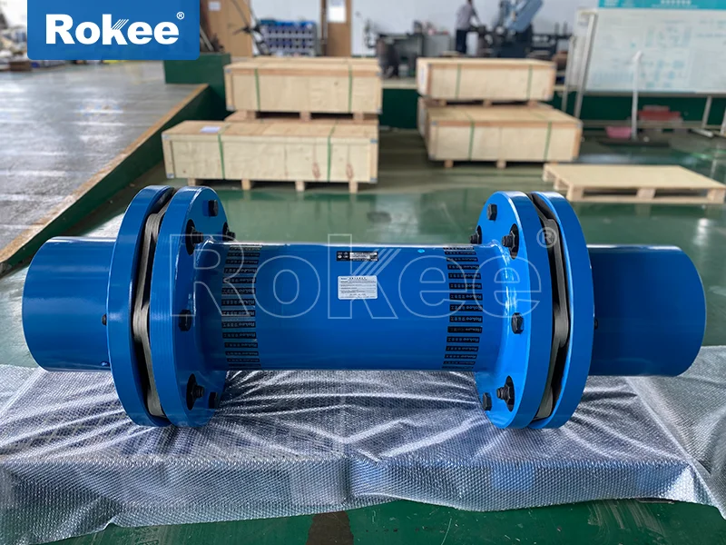
Flexible membrane coupling is a high-performance coupling device that uses metal elastic elements to compensate for the relative displacement between two shafts through the elastic deformation of stainless steel thin plate diaphragm groups. The flexible membrane coupling belongs to the category of seamless metal flexible couplings, and its core design concept is to use the elastic properties of metal materials to achieve a perfect combination of power transmission and deviation compensation.
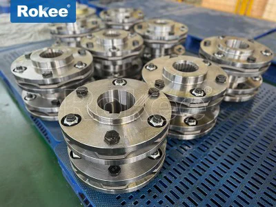
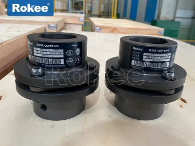
The flexible membrane coupling mainly consists of three parts: two half couplings with wheel hubs, one or more sets of stainless steel diaphragms, and connecting bolts. The membrane is usually made of high-strength stainless steel, and each set of membranes is composed of several (usually 4-12) ultra-thin stainless steel sheets stacked together, which are fixed to the two halves of the coupling by precision bolts in a staggered manner. According to the compensation capability requirements, the membrane can be designed in different shapes such as linkage or integral, with linkage providing better flexibility and integral providing higher torsional stiffness.
The working principle of flexible membrane coupling: When the driving shaft rotates, torque is transmitted to the diaphragm through the bolt group, and then transmitted to the driven shaft through the diaphragm. When there is relative displacement between the two axes, the diaphragm absorbs these deviations through its own elastic deformation - radial displacement causes the diaphragm to undergo tensile or compressive deformation, angular displacement causes the diaphragm to undergo bending deformation, and axial displacement causes the diaphragm to undergo planar deformation. This elastic deformation mechanism enables the coupling to achieve deviation compensation without any sliding parts, fundamentally avoiding wear problems.
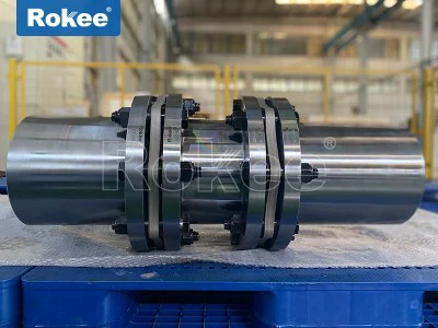
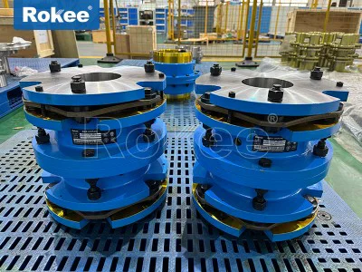
Classification: According to the number of membrane groups, it can be divided into two types: single membrane and double membrane. The single diaphragm coupling has a simple and compact structure, suitable for situations with small deviations, and can usually withstand angular deviations of about 0.5-1 degrees; The double diaphragm coupling adds a rigid element in the middle, and the two sets of diaphragms can bend in different directions, significantly improving the compensation ability. It can handle larger radial and angular deviations (radial deviation can reach 1.5mm, angular deviation can reach 1.5 degrees), especially suitable for installation environments with poor centering conditions.
Compared with traditional couplings, flexible membrane couplings have revolutionary advantages such as no lubrication, no wear, and zero backlash. Metal diaphragms do not age and fail like rubber or plastic elastomers, nor do they require regular lubrication like gear couplings, which makes them outstanding in terms of maintenance free performance. Meanwhile, the all metal structure enables it to operate stably within the extreme temperature range of -80 ° C to+300 ° C and withstand corrosive media environments, greatly expanding its application scenarios.
The reason why flexible membrane couplings can quickly replace traditional couplings in many industrial fields is due to their excellent mechanical properties and unique technological advantages. These characteristics make it an ideal choice for high-precision, high-speed, and heavy-duty working conditions.
Powerful deviation compensation capability: The diaphragm coupling can simultaneously compensate for three types of deviations: axial, radial, and angular. Its angular compensation capability can reach twice that of traditional gear couplings. When radial deviation occurs, the reaction force generated by the coupling is small and the system flexibility is large. Typical parameters are: axial displacement ± 0.5-5mm, radial displacement 0.2-1.5mm, angular displacement 0.5 ° -1.5 °. This multi-directional compensation capability is particularly suitable for situations where shaft alignment is difficult due to foundation settlement, thermal expansion, or manufacturing and installation errors.
Excellent vibration reduction and transmission performance: The metal diaphragm can effectively absorb vibration energy while transmitting torque, ensuring smooth and noise free system operation. Tests have shown that diaphragm couplings can reduce system vibration amplitude by up to 30% -50%. Its transmission efficiency is as high as 99.86%, with almost no power loss, which is significantly higher than most flexible couplings. More importantly, it can accurately transmit rotational speed without any slip during operation, and can even be used for precision mechanical transmissions with strict requirements, such as CNC machine tool spindles and measuring equipment.
Environmental adaptability and durability: The membrane made of stainless steel material has excellent corrosion resistance and can resist corrosion from acidic and alkaline media. The all metal structure does not require lubrication, avoiding oil pollution problems, and is particularly suitable for industries with high cleanliness requirements such as food and medicine. The product has a wide working temperature range, with conventional models ranging from -80 ° C to+300 ° C. Specially designed couplings can even adapt to deep cold environments of -196 ° C or high temperature conditions of+350 ° C. It can still operate safely under impact vibration conditions, and its service life can usually reach 10-20 years, far exceeding that of general elastic couplings.
Structural and maintenance advantages: The diaphragm coupling has a compact structure, light weight, and small installation space. The design with an intermediate shaft allows the equipment to be assembled and disassembled without moving, greatly simplifying maintenance work. Due to the absence of friction components that move relative to each other, the coupling is essentially maintenance free and only requires regular inspections of bolt tightening status and membrane for cracks, significantly reducing the overall cost of ownership.
From a technological development perspective, modern diaphragm couplings have continuously improved their performance through finite element optimization design and advanced material applications. If high-strength nickel alloy membrane is used, the fatigue life can be extended by 30%; Special surface treatment techniques such as nitriding and shot peening can significantly improve the wear resistance and corrosion resistance of the membrane; By using dynamic balance correction (with an accuracy of G2.5 level), the coupling can operate more smoothly at high speeds, and these technological advancements continue to expand the application boundaries of diaphragm couplings.
After years of development, flexible membrane couplings have formed a rich product line, with significant differences in structural design, size specifications, and performance characteristics among various models to meet the application needs of different industrial scenarios. Understanding the classification and characteristics of these models is crucial for proper selection.
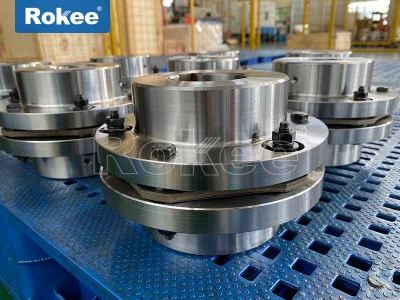
DJM single key slot coupling film: adopting a single membrane design and key slot connection method, the structure is the simplest and most compact, suitable for medium torque transmission occasions with limited space. The nominal torque range is usually 10-5000Nm, and the shaft hole diameter ranges from 6mm to 120mm. This model has strong axial displacement compensation capability, but relatively limited angular compensation capability (about 0.5 degrees), making it suitable for installing equipment with high centering accuracy.
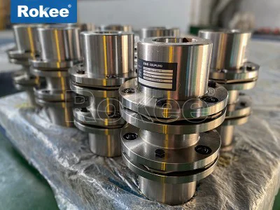
DJM-T expansion sleeve coupling: Innovatively using expansion sleeve connection technology instead of traditional key connection, the expansion sleeve forms an interference fit with the shaft through high-strength bolts, achieving keyless connection. This design eliminates stress concentration caused by keyways, making installation and positioning more precise. It is particularly suitable for situations that require frequent disassembly or high-precision positioning, such as the connection between servo motors and ball screws. The typical application torque range is 50-8000Nm.
ZJM cone sleeve coupling with double diaphragm coupling: Combining the advantages of cone shaft sleeve and double diaphragm structure, the cone sleeve design provides better installation centering, while the double diaphragm group provides greater deviation compensation capability. This model is particularly suitable for large power units such as ship propulsion systems, heavy-duty compressors, etc. Its nominal torque can reach over 50000Nm, and the maximum shaft hole diameter can reach 300mm. The cone sleeve connection can also effectively prevent micro motion wear between the shaft and the hub.
TJM external clamping diaphragm coupling: adopting a unique clamping wheel hub design, the shaft diameter is directly clamped from the outside through high-strength bolts, eliminating the keyway machining process and making installation more convenient. This structure transmits torque evenly, does not damage the shaft surface, and has automatic centering characteristics. There are two variants: single diaphragm (TJM) and double diaphragm (TJMJ). The former is suitable for small servo systems, while the latter is used for medium-sized transmission systems that require higher deviation compensation capabilities.
JM Micro Diaphragm Coupling: Designed specifically for precision small equipment, with a minimum outer diameter of up to 12mm and a torque range of 0.1-100Nm, it is widely used in micro transmission fields such as stepper motors, encoders, laboratory instruments, etc. Although these types of couplings are small in size, they still maintain the characteristics of zero backlash and high rigidity of diaphragm couplings.
In recent years, modular design has become a trend, such as the F-type diaphragm coupling, which combines the compactness of the R-type and the ability to accommodate large shaft diameters of the G-type. The same specification can be adapted to multiple shaft diameters, significantly improving product versatility. Specially designed for ultra high speed applications, such as the 8-cornea structure (replacing the conventional 6-cornea structure), enables more uniform torque transmission, with a maximum speed of up to 30000 rpm, meeting the demanding requirements of high-end fields such as turbomachinery and aviation engines.
The flexible membrane coupling is subjected to complex load combinations during operation, and accurate analysis of these stress conditions is crucial for ensuring reliable operation and extending the service life of the coupling. As the core elastic element of the coupling, the stress state of the diaphragm group directly determines the performance of the entire coupling.
Thin film stress generated by torque: When the coupling transmits torque T (N · m), for a typical structure with m groups of diaphragms and 8-hole bolts, the torque T1 borne by each group of diaphragms is T/m. Through mechanical analysis, it can be concluded that the force acting on each main bolt is F=T/(4mR), where R is the radius of the bolt distribution circle. This force causes shear stress and in-plane tensile stress on the membrane, which are proportional to the transmitted torque and inversely proportional to the square of the membrane thickness and quantity. Modern finite element analysis shows that the maximum stress usually occurs near the hinge point between the diaphragm and the hub, which is prone to stress concentration and is a common starting point for fatigue cracks.
Centrifugal stress: The centrifugal inertia force generated by various components of the coupling during high-speed rotation cannot be ignored. When calculating, the mass and position of the bolt and diaphragm need to be considered. The centrifugal force F=(2 π n/60) ² rp, where n is the rotational speed (rpm), r is the mass radius, and p is the mass. These centrifugal forces acting radially outward will cause additional tensile stress in the membrane. Especially when the speed exceeds 10000rpm, centrifugal stress may become the dominant factor, which is why high-speed couplings typically use lightweight aluminum alloy wheels and high-strength thin film sheets. By fixing the radial, circumferential, and axial displacement boundary conditions of the middle bolt hole, the stress distribution under this working condition can be accurately simulated.
Bending stress caused by axial deviation: Axial deviation during installation can cause bending deformation of the diaphragm along the axis direction. Applying this displacement load in the axial direction of the middle bolt hole, while fixing the radial and axial displacements, can establish a static simply supported mechanism model for analysis. Research has shown that the stress on the diaphragm caused by axial deviation is linearly related to the amount of deviation and inversely proportional to the square of the diaphragm length. Therefore, for applications that may generate significant axial displacement, such as steam turbines with significant thermal expansion, diaphragm couplings with longer intermediate sections should be selected to reduce bending stress.
Angular deviation stress: Angular installation errors cause periodic bending deformation of the diaphragm, which is the main cause of fatigue failure. The magnitude of the restoring moment H can be calculated by tilting the angle. Since the angular displacement of the diaphragm is usually very small (<1.5 °), the thin plate small deflection bending theory can be used for analysis. In practical engineering, the amplitude of alternating stress generated by angular deviation is often much greater than the average stress, which makes the fatigue life of the diaphragm extremely sensitive to the installation accuracy. Experimental data shows that when the angular deviation increases from 0.5 ° to 1 °, the lifespan of the membrane may be shortened by 60% -70%.
The stress concentration factor (Kt) is crucial in the design of diaphragm couplings. There are usually high Kt values (2.0-3.5) at the edges of bolt holes and transition corners on the membrane. By optimizing the geometric shape, such as using variable thickness design or stress relief grooves, Kt can be reduced to below 1.5. The latest design trend is to add reinforcement patches in high stress areas. Finite element analysis shows that this structure can reduce peak stress by 30% -40% and significantly extend service life.
Other stress factors need to be considered for special application environments. For example, in the propulsion system of a ship, the coupling may bear impact loads, and the instantaneous peak stress needs to be checked; In the petrochemical industry, the combined effect of corrosive media and stress may cause stress corrosion cracking, requiring the selection of corrosion-resistant materials and control of surface stress levels. Through comprehensive force analysis and precise calculation, the diaphragm coupling can ensure safe and reliable operation under various working conditions. The typical safety factor is generally taken as 2-3 (based on yield strength) or 4-6 (based on fatigue limit).
Proper installation and standardized maintenance are key factors in ensuring optimal performance and extending the service life of flexible membrane couplings. Unlike traditional couplings, diaphragm couplings have higher requirements for installation accuracy and operating procedures, and any improper operation may lead to premature failure or performance degradation.
Installation Guide
Pre installation inspection: Before installation, thoroughly clean the shaft end and coupling inner hole, check whether the shaft diameter size and keyway fit meet the requirements, and remove all burrs and sharp corners. Measure and record the actual dimensions of the shaft diameter and coupling hole to ensure that the interference fit is within a reasonable range (usually H7/k6 or H7/m6 mating). For precision equipment, it is recommended to use a dial gauge to check the radial runout (generally ≤ 0.02mm) and end face runout (generally ≤ 0.01mm/m) of the shaft end.
Axis deviation control: The axial, radial, and angular deviations that the coupling can compensate for are strictly limited. During installation, it is necessary to use a laser centering instrument or dual meter method for precise adjustment to ensure that the deviation is within the allowable range (usually radial ≤ 0.1mm, angular ≤ 0.5 °). When multiple deviations coexist, the total compensation capability will decrease, and each deviation should be controlled within 1/3 of the standard value. It should be noted that although diaphragm couplings can compensate for certain deviations, the ideal centering state can maximize their lifespan.
Bolt tightening process: The bolts of the diaphragm coupling must be tightened in stages in diagonal order. Firstly, pre tighten all bolts by hand, then use a torque wrench to evenly tighten them in three stages of 1/4, 1/2, and 3/4 of the rated torque, and finally fully tighten them to the rated torque (usually 70% -80% of the material yield strength). After tightening, it is recommended to apply anti loosening glue to the threaded part of the bolt. It is absolutely forbidden to use pneumatic tools for direct fastening to avoid overloading.
Maintain standards
Regular inspection: After 8 hours of operation, all bolts of the newly installed coupling should be tightened again, and then checked every 500 hours of operation thereafter. Focus on checking whether there are cracks or deformations in the membrane, whether the bolts are loose, and whether there are signs of relative sliding in the wheel hub. For high-speed equipment (>3000rpm), it is recommended to conduct vibration testing once a month to determine the coupling status through spectrum analysis.
Lubrication and anti-corrosion: Although the diaphragm coupling itself does not require lubrication, the supporting shaft extension, keyway and other parts should be regularly coated with an appropriate amount of lubricating grease. In corrosive environments, the surface of the membrane can be coated with molybdenum disulfide or treated with Teflon, which can reduce micro motion wear and enhance corrosion resistance. Couplings used in coastal areas require special attention to prevent stress corrosion caused by chloride ions.
In modern industrial transmission systems, flexible membrane couplings have emerged as essential components that bridge the gap between driving and driven shafts, enabling efficient power transfer while accommodating various forms of misalignment. Unlike traditional coupling devices that rely on sliding parts or elastic rubber elements, these couplings utilize the elastic deformation of metal diaphragms to achieve both torque transmission and deviation compensation, making them a preferred choice in a wide range of industrial applications. Their unique design combines compact structure, high reliability, and minimal maintenance requirements, distinguishing them from other types of couplings and ensuring their widespread adoption in sectors such as aerospace, automotive, machinery manufacturing, and chemical engineering. To fully understand the value and functionality of flexible membrane couplings, it is necessary to explore their structural composition, core performance characteristics, classification based on design and application needs, and the diverse scenarios where they play a critical role.
The structure of a flexible membrane coupling is relatively compact yet meticulously designed to fulfill its dual functions of torque transmission and misalignment compensation, consisting of three core components that work in harmony to ensure stable operation. The first and most fundamental component is the two half-couplings, which are typically connected to the driving and driven shafts respectively. These half-couplings are usually fabricated from high-strength materials such as carbon steel, alloy steel, or aluminum alloy, depending on the specific torque and environmental requirements of the application. The choice of material for the half-couplings is crucial as it directly affects the coupling’s overall load-bearing capacity and durability; for instance, alloy steel half-couplings are often used in high-torque applications, while aluminum alloy variants are preferred for lightweight and high-speed scenarios. Each half-coupling is equipped with a hub that fits tightly onto the shaft, and the connection between the hub and the shaft is commonly achieved through keyways, interference fits, or expansion sleeves, ensuring that there is no relative slip between the shaft and the coupling during operation. Some specialized designs may also incorporate anti-loosening structures to prevent the half-couplings from detaching from the shafts under high-speed rotation or vibration.
The second and most distinctive component of a flexible membrane coupling is the diaphragm group, which serves as the elastic element responsible for compensating for shaft misalignment. The diaphragms are thin, flexible metal sheets, usually made of high-quality stainless steel, inconel, or titanium alloy, materials known for their excellent elastic properties, corrosion resistance, and fatigue strength. Stainless steel is the most commonly used material for diaphragms due to its balance of cost, flexibility, and durability, making it suitable for most industrial environments. In contrast, inconel and titanium alloy diaphragms are utilized in extreme conditions, such as high-temperature or high-corrosion environments, where stainless steel may not withstand the operational stresses. Each diaphragm group typically consists of several (usually 4 to 12) ultra-thin metal sheets stacked together, which are fixed to the two half-couplings using precision bolts in a staggered arrangement. This staggered bolting design ensures that the torque is evenly distributed across the entire diaphragm group, reducing stress concentration and extending the service life of the diaphragms. The shape of the diaphragms can vary based on the compensation requirements; common designs include link-type and integral-type diaphragms, with link-type diaphragms offering greater flexibility and integral-type diaphragms providing higher torsional stiffness.
The third component is the connecting bolts, which play a critical role in securing the diaphragm group to the half-couplings. These bolts are usually high-strength fasteners made of alloy steel,经过 heat treatment to enhance their tensile strength and fatigue resistance. The bolts must be precisely sized and tightened to a specific torque to ensure that the diaphragms are held securely without excessive compression, which could restrict their elastic deformation. In some designs, sleeves are installed between the bolts and the diaphragm holes to reduce stress concentration around the holes, preventing the diaphragms from cracking due to repeated deformation. Additionally, the bolts are often arranged in a circular pattern around the hub of the half-couplings, ensuring that the force is evenly distributed and that the torque is transmitted smoothly from one half-coupling to the diaphragm group and then to the other half-coupling. Together, these three components form a cohesive structure that enables the flexible membrane coupling to transmit torque efficiently while accommodating small amounts of axial, radial, and angular misalignment between the two shafts.
The performance of flexible membrane couplings is defined by a set of core characteristics that make them suitable for a wide range of industrial applications, distinguishing them from other coupling types such as gear couplings, elastic sleeve pin couplings, and universal couplings. One of the most prominent performance features is their excellent misalignment compensation capability, which allows them to accommodate three types of misalignment: axial, radial, and angular. Axial misalignment occurs when the two shafts are displaced along their common axis, radial misalignment is the lateral displacement of the shafts, and angular misalignment is the tilt between the two shafts. The diaphragms absorb these deviations through their elastic deformation: radial displacement causes the diaphragm to undergo tensile or compressive deformation, angular displacement leads to bending deformation, and axial displacement results in planar deformation. This elastic deformation mechanism enables the coupling to compensate for misalignment without any sliding parts, fundamentally avoiding wear problems that are common in gear couplings, which rely on sliding gears to accommodate misalignment. The amount of misalignment that a flexible membrane coupling can accommodate depends on factors such as the material of the diaphragms, the number of diaphragms in the group, and the design of the coupling, but most standard models can compensate for axial misalignment of ±0.5 to ±5 mm, radial misalignment of 0.1 to 1 mm, and angular misalignment of 0.1° to 1°.
Another key performance characteristic is the high torque transmission efficiency of flexible membrane couplings. Due to their rigid connection between the half-couplings and the diaphragms, there is no relative slip during operation, resulting in a transmission efficiency of over 99.5%, which is significantly higher than that of elastic sleeve pin couplings (which typically have an efficiency of 95% to 98%). This high efficiency is particularly important in applications where energy conservation is a priority, such as in electric motors, pumps, and fans, as it reduces energy loss and improves the overall efficiency of the transmission system. Additionally, flexible membrane couplings have high torsional stiffness, which means that they can transmit torque without significant torsional deformation, ensuring that the rotation of the driven shaft is synchronized with the driving shaft. This is crucial in precision applications such as machine tools, robotics, and aerospace equipment, where precise torque transmission and position control are essential.
Durability and long service life are also important performance features of flexible membrane couplings. Since they have no sliding parts or wearing components (such as bearings or rubber sleeves), they require minimal maintenance and have a longer service life compared to other coupling types. The diaphragms, which are the only elastic elements, are made of high-strength metal materials with excellent fatigue resistance, enabling them to withstand repeated elastic deformation over a long period without failure. Under normal operating conditions, a well-designed flexible membrane coupling can have a service life of 5 to 10 years, significantly reducing the frequency of replacement and maintenance costs. Additionally, flexible membrane couplings are resistant to high temperatures, corrosion, and harsh environments. The metal diaphragms and half-couplings can withstand operating temperatures ranging from -40°C to 250°C (and even higher for specialized materials such as inconel), making them suitable for applications in high-temperature environments such as steam turbines, internal combustion engines, and industrial furnaces. They are also resistant to oil, grease, chemicals, and moisture, making them ideal for use in the chemical, petroleum, and marine industries, where corrosive substances are present.
Low vibration and noise levels are another notable performance advantage of flexible membrane couplings. Due to their rigid structure and the absence of sliding parts, they operate smoothly with minimal vibration, which helps to reduce noise pollution and protect the connected equipment from vibration-induced damage. This is particularly important in applications such as precision machinery, medical equipment, and indoor industrial environments, where low noise and vibration are required. In contrast, gear couplings produce significant noise due to the meshing of gears, and elastic sleeve pin couplings can generate vibration as the rubber sleeve wears over time.
Flexible membrane couplings can be classified into several types based on various criteria, including the number of diaphragm groups, the structure of the diaphragms, the design of the half-couplings, and the application scenario. The most common classification is based on the number of diaphragm groups, which divides them into single-membrane and double-membrane (or multi-membrane) couplings. Single-membrane couplings consist of a single set of diaphragms connected between two half-couplings, featuring a simple structure, light weight, and low cost. They are primarily used in applications where the misalignment between the shafts is small, the torque is low to moderate, and space is limited. Typical applications of single-membrane couplings include small motors, fans, pumps, and light-duty machinery, where their compact design and sufficient misalignment compensation capability meet the operational requirements. However, single-membrane couplings have limited misalignment compensation capacity compared to double-membrane types, and they may transmit more axial force to the connected shafts, which can affect the service life of bearings.
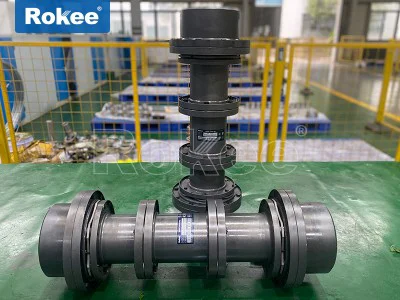
Double-membrane couplings, on the other hand, consist of two sets of diaphragms separated by an intermediate shaft or spacer. This design significantly enhances the misalignment compensation capability, particularly for angular and axial misalignment, as the two diaphragm groups can deform independently to absorb deviations. The intermediate shaft also helps to reduce the axial force transmitted to the connected shafts, protecting the bearings and other components of the transmission system. Double-membrane couplings have higher torsional stiffness and torque transmission capacity than single-membrane types, making them suitable for high-torque, heavy-duty applications such as compressors, agitators, crushers, and large-scale pumps. They are also used in applications where the distance between the two shafts (the span) is relatively large, as the intermediate shaft can be adjusted to accommodate different span requirements. Some double-membrane couplings may also incorporate a floating intermediate shaft, which further improves the misalignment compensation capability and reduces stress on the diaphragms.
Another classification criterion is the structure of the diaphragms, which includes link-type, integral-type, and segmented-type diaphragms. Link-type diaphragms are composed of several individual links connected together, forming a flexible structure that can easily deform to accommodate misalignment. They offer high flexibility and are suitable for applications where large angular misalignment is expected. Integral-type diaphragms are a single, continuous sheet of metal with a specific shape (such as a disc or a bellows) that allows for elastic deformation. They have higher torsional stiffness and are more resistant to fatigue compared to link-type diaphragms, making them suitable for high-speed and high-torque applications such as machine tools and aerospace equipment. Segmented-type diaphragms are composed of several segments of metal sheets connected in a circular pattern, combining the flexibility of link-type diaphragms with the stiffness of integral-type diaphragms. They are often used in applications where a balance between flexibility and stiffness is required, such as in automotive transmissions and industrial gearboxes.
Flexible membrane couplings can also be classified based on the design of the half-couplings, including split-type and integral-type half-couplings. Split-type half-couplings are composed of two separate halves that are fastened together with bolts, allowing for easy installation and removal without moving the connected shafts. This is particularly convenient in applications where the shafts are already installed or where maintenance is frequent, such as in pumps and compressors. Integral-type half-couplings are a single, one-piece component that is mounted onto the shaft using an interference fit or keyway connection. They have higher rigidity and are more suitable for high-speed and high-torque applications, as they eliminate the potential for misalignment caused by the split joint. Additionally, some specialized designs include keyless type half-couplings, which use expansion sleeves to connect to the shaft, enabling quick installation and removal and providing a secure, slip-free connection.
The diverse performance characteristics and structural designs of flexible membrane couplings make them suitable for a wide range of applications across various industries, from general industrial machinery to high-precision and extreme-environment equipment. In the aerospace industry, flexible membrane couplings are used in aircraft engines, helicopter transmissions, and satellite systems, where high reliability, high torque transmission efficiency, and resistance to extreme temperatures and vibrations are essential. The compact design and low weight of these couplings make them ideal for aerospace applications, where every gram of weight savings is critical. For example, in aircraft engines, flexible membrane couplings connect the turbine to the compressor, transmitting high torque while accommodating small amounts of misalignment caused by thermal expansion and vibration, ensuring the stable operation of the engine.
In the automotive industry, flexible membrane couplings are used in transmissions, drive shafts, and electric vehicle powertrains. They are particularly suitable for electric vehicles, where high efficiency, low noise, and precise torque transmission are required. The absence of sliding parts and minimal maintenance requirements make them ideal for electric vehicle applications, as they reduce the overall weight and complexity of the powertrain. Additionally, flexible membrane couplings are used in hybrid vehicles, where they connect the internal combustion engine to the electric motor, enabling smooth power transfer between the two systems.
The machinery manufacturing industry is one of the largest users of flexible membrane couplings, where they are used in a wide range of equipment, including machine tools, robotics, conveyors, and crushers. In machine tools, such as CNC lathes, milling machines, and grinding machines, flexible membrane couplings are used to connect the motor to the spindle, ensuring precise torque transmission and position control. The high torsional stiffness and low vibration of these couplings help to improve the machining accuracy and surface quality of the workpieces. In robotics, flexible membrane couplings are used in the joints of industrial robots, enabling smooth and precise movement while accommodating small amounts of misalignment caused by the robot’s motion. They are also used in conveyors, where they connect the motor to the conveyor belt, transmitting torque efficiently while accommodating misalignment caused by the installation of the conveyor components.
In the chemical and petroleum industries, flexible membrane couplings are used in pumps, compressors, mixers, and reactors, where they must withstand corrosive environments, high temperatures, and high pressures. The corrosion resistance of the metal diaphragms and half-couplings makes them suitable for use with chemicals such as acids, alkalis, and solvents, while their high-temperature resistance enables them to operate in environments where temperatures exceed 200°C. For example, in chemical pumps, flexible membrane couplings connect the motor to the pump impeller, transmitting torque while accommodating misalignment caused by the thermal expansion of the pump casing and the shaft. In compressors, they are used to connect the motor to the compressor rotor, ensuring efficient power transfer and stable operation under high pressure.
The power generation industry also relies heavily on flexible membrane couplings, where they are used in steam turbines, gas turbines, and wind turbines. In steam and gas turbines, flexible membrane couplings connect the turbine to the generator, transmitting high torque while accommodating misalignment caused by thermal expansion and vibration. The high efficiency and reliability of these couplings are critical for ensuring the stable operation of the power generation system, as any failure could result in significant power outages. In wind turbines, flexible membrane couplings are used in the nacelle, connecting the rotor to the gearbox and the gearbox to the generator. They must withstand high torque, variable loads, and harsh environmental conditions such as strong winds, temperature fluctuations, and moisture, making them an essential component of wind energy systems.
In addition to these major industries, flexible membrane couplings are also used in a variety of other applications, including medical equipment, food processing machinery, and marine equipment. In medical equipment, such as centrifuges and diagnostic machines, flexible membrane couplings are used to ensure precise torque transmission and low vibration, which is critical for the accuracy of the equipment. In food processing machinery, they are used in mixers, conveyors, and packaging equipment, where they must be easy to clean and maintain to meet food hygiene standards. In marine equipment, such as ship propellers and marine engines, flexible membrane couplings are used to connect the engine to the propeller, transmitting torque efficiently while accommodating misalignment caused by the movement of the ship and the thermal expansion of the engine components.
When selecting a flexible membrane coupling for a specific application, several factors must be considered to ensure optimal performance and reliability. These factors include the torque requirement, the speed of the shafts, the amount and type of misalignment, the operating temperature and environment, and the installation space. The torque capacity of the coupling must be sufficient to handle the maximum torque generated by the driving shaft, with a safety margin to account for unexpected load fluctuations. The speed of the coupling must also be compatible with the rotational speed of the shafts, as excessive speed can cause the diaphragms to fail due to centrifugal force. The misalignment compensation capability of the coupling must match the expected misalignment between the two shafts, to prevent excessive stress on the diaphragms and the connected equipment. The operating temperature and environment will determine the choice of material for the diaphragms and half-couplings, with specialized materials required for high-temperature or corrosive environments. Finally, the installation space must be considered to ensure that the coupling fits within the available dimensions, with compact designs preferred for applications where space is limited.
In conclusion, flexible membrane couplings are versatile and high-performance transmission components that play a critical role in modern industrial systems. Their unique structure, consisting of half-couplings, diaphragm groups, and connecting bolts, enables them to transmit torque efficiently while accommodating axial, radial, and angular misalignment. Their core performance characteristics, including high transmission efficiency, excellent misalignment compensation, durability, low vibration, and resistance to harsh environments, make them superior to other types of couplings in many applications. The diverse types of flexible membrane couplings, classified based on the number of diaphragm groups, diaphragm structure, and half-coupling design, allow them to be tailored to a wide range of industrial needs. From aerospace and automotive to machinery manufacturing and power generation, flexible membrane couplings are essential for ensuring the stable, efficient, and reliable operation of transmission systems. As industrial technology continues to advance, the design and performance of flexible membrane couplings will continue to evolve, enabling them to meet the increasingly demanding requirements of modern industrial applications.