Working Principle Of Cardan Shaft Coupling

Universal shaft coupling is a critical mechanical transmission device, whose core function is to achieve reliable transmission of torque and rotational motion when there is an angular deviation between the two shafts.
Working principle
Universal couplings connect the driving shaft and the driven shaft through cardan shaft couplings (such as cross shafts or cage structures). When the active shaft rotates, the special geometric structure of the cardan shaft coupling allows the two shafts to deflect within an angle range of 5 °~45 ° while maintaining the continuity of motion.
Through the articulated structure of the cardan shaft coupling, axial, radial, and angular deviations can be compensated for, adapting to equipment installation errors or displacement changes during operation.
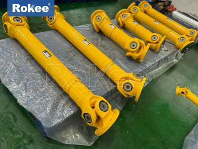
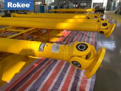
Cross axis cardan shaft coupling
Structure: Composed of two fork shaped joints and a cross shaft, the bearings are made of needle rollers or sliding bearings.
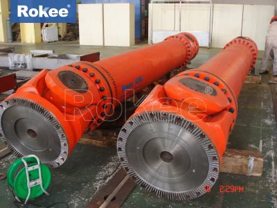
Characteristics: Strong load-bearing capacity (suitable for heavy-duty low-speed scenarios), but prone to vibration due to centrifugal force at high speeds.
Application: Engineering machinery, metallurgical rolling mills, etc.
Ball cage cardan shaft coupling
Structure: The spherical shell contains steel balls and a cage, which transmit torque through the ball path.
Features: Smooth transmission, high speed, but high manufacturing cost.
Applications: Automotive drive shafts, precision machine tools.
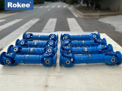
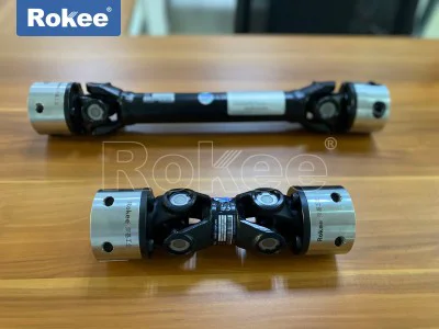
Double cardan shaft coupling
Design optimization: The intermediate shaft adopts a modular and detachable structure to improve maintenance efficiency.
Advantage: Eliminating speed fluctuations of single cardan shaft couplings, suitable for long-distance transmission.
Application scenarios
Automotive industry: The transmission shaft connects the gearbox and drive axle to adapt to wheel runout.
Construction machinery: excavator slewing mechanism, crane boom articulated.
Metallurgical equipment: Rolling mill roll system transmission, compensating for axis deviation during roll adjustment.
Aerospace: Helicopter rotor transmission system, solving the problem of misalignment between the engine and rotor shaft.
The design of the cardan shaft coupling cleverly combines the principles of mechanical geometry and dynamics, and its diverse structural forms provide flexible transmission solutions for modern industrial equipment.
In the realm of mechanical power transmission, the Cardan shaft coupling, also widely referred to as a universal joint coupling, stands as a fundamental and indispensable component designed to address a pervasive challenge in machinery operation: the efficient transfer of torque and rotational motion between two shafts that are not perfectly aligned. Unlike rigid couplings that demand precise coaxial alignment of driving and driven shafts, the Cardan shaft coupling introduces a degree of angular flexibility, enabling reliable power delivery even when the central axes of the two shafts intersect at a measurable angle, shift radially, or experience minor axial displacement during operation. This unique capability stems from its specialized mechanical structure and the kinematic principles that govern its motion, making it a staple in countless industrial, automotive, and heavy machinery systems where shaft misalignment is unavoidable due to manufacturing tolerances, assembly errors, thermal expansion, or dynamic load-induced movement.
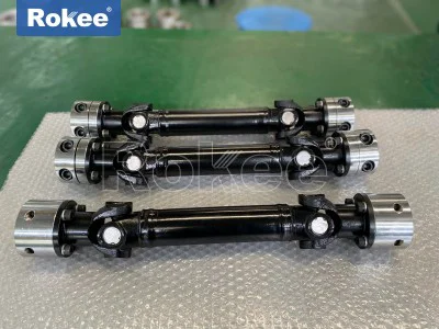
At its most basic configuration, a standard single Cardan shaft coupling is composed of three primary interconnected elements: two yoke-shaped end fittings and a central cross-shaped member, commonly known as a spider. Each yoke is a robust, U-shaped mechanical component engineered to attach securely to the driving shaft and the driven shaft respectively, typically via rigid connections such as splines, flanges, or keyed joints that eliminate slippage and ensure full torque transfer. The spider, positioned at the junction of the two yokes, features four perpendicular arms that fit precisely into bearing housings machined into the open ends of each yoke. These bearing interfaces are critical, as they facilitate smooth rotational and oscillatory movement between the spider and the yokes, minimizing friction and wear while maintaining mechanical rigidity. The geometric arrangement of these parts is non-negotiable: the rotational axes of the two yokes intersect at the exact center of the spider, and the arms of the spider are oriented at 90 degrees to one another, creating a universal pivot point that allows the yokes to move independently within a defined angular range. This simple yet elegant structure is the foundation upon which the entire working principle of the Cardan shaft coupling is built, as it transforms the constrained motion of aligned shafts into adaptable motion for misaligned shafts without interrupting power flow.
The core working principle of the Cardan shaft coupling revolves around the transmission of rotational motion and torque through articulated, multi-directional movement, with the spider acting as the intermediary that bridges the angular gap between the two shafts. When the driving shaft is set into rotation by a power source—such as an engine, motor, or gearbox—the attached driving yoke rotates in unison with the shaft, transferring this rotational force to the adjacent arms of the spider. Because the spider is free to pivot within the bearing sockets of both yokes, it does not merely rotate but also oscillates to accommodate the angular offset between the driving and driven shafts. This oscillatory rotation of the spider then transmits the motion to the driven yoke, which in turn transfers the torque and rotational speed to the driven shaft. Crucially, this process occurs continuously throughout a full 360-degree rotation of the driving shaft, with the spider adjusting its position dynamically to maintain contact and force transmission between the two yokes. Unlike rigid connections that would bind, bend, or break under angular misalignment, the Cardan coupling’s articulated design allows the two shafts to operate at a consistent angle relative to one another, typically ranging from a few degrees up to 45 degrees depending on the specific design and size of the coupling, while sustaining smooth and uninterrupted power transmission.
A key consideration in understanding the working principle of the single Cardan shaft coupling is its non-constant velocity characteristic, a kinematic trait that arises directly from its articulated structure and angular misalignment. When the driving shaft rotates at a uniform, constant angular velocity, the driven shaft does not replicate this speed precisely; instead, its angular velocity fluctuates periodically within each full rotation. This variation is a direct result of the changing leverage and angular relationship between the spider arms and the yokes as the coupling rotates. At specific points in the rotation cycle, the effective radius of torque transmission shifts, causing the driven shaft to speed up slightly and slow down in a repetitive, sinusoidal pattern. The magnitude of this speed fluctuation is directly proportional to the operating angle between the two shafts: a smaller angle results in minimal velocity variation, while a larger angle amplifies the fluctuation, leading to increased vibration, dynamic stress, and wear on the coupling and surrounding shaft components. This phenomenon does not impede the basic function of torque transmission, but it does limit the suitability of single Cardan couplings for high-speed, precision-critical applications where smooth, consistent rotational output is required. It is this limitation that spurred the development of modified Cardan shaft designs, which leverage the same core working principle but add structural refinements to mitigate velocity fluctuations.
To address the non-constant velocity issue of single Cardan couplings, the double Cardan shaft coupling was engineered, building on the fundamental working principle of articulated torque transfer while introducing a phase-offset mechanism to neutralize speed variations. A double Cardan assembly consists of two single Cardan joints connected by a short intermediate shaft, with the two joints positioned at a 90-degree phase shift relative to one another. The key to its operation lies in balancing the angular velocity fluctuations generated by each individual joint: the velocity irregularities produced by the first joint (closest to the driving shaft) are exactly counteracted by the opposing fluctuations produced by the second joint (closest to the driven shaft), provided that the operating angles between the driving shaft and intermediate shaft, and between the intermediate shaft and driven shaft, are equal. In this configuration, the driven shaft ultimately rotates at the same constant angular velocity as the driving shaft, eliminating unwanted vibration and dynamic loading. This design retains the core advantage of angular misalignment compensation—allowing the driving and driven shafts to be offset at a significant combined angle—while delivering the smooth rotational performance of a rigid coupling. The working principle remains rooted in the spider-yoke articulation of the basic Cardan joint, but the dual-joint, phase-shifted setup transforms a non-constant velocity transmission into a near-constant velocity system, expanding its applicability to high-speed machinery, precision equipment, and systems where vibration control is paramount.
Beyond angular misalignment compensation, the working principle of the Cardan shaft coupling extends to accommodate additional forms of shaft displacement, further enhancing its versatility in real-world mechanical systems. While its primary function is addressing angular offset, the inherent flexibility of the spider-yoke joint also allows for limited radial misalignment, where the central axes of the driving and driven shafts run parallel but are offset horizontally, as well as minor axial displacement, where the shafts move slightly toward or away from one another along their central axes. This multi-faceted displacement compensation is not a secondary feature but a natural extension of the coupling’s articulated kinematics; the pivoting action of the spider within the yokes absorbs small radial and axial shifts without compromising torque transmission or causing mechanical stress. This adaptability is vital in industrial machinery, where shafts are often subjected to thermal growth, foundation settling, or dynamic load-induced movement during operation. The Cardan coupling’s ability to handle these combined displacement types ensures that power transmission remains efficient and reliable, reducing the risk of premature component failure, shaft bending, or bearing damage that would occur with rigid couplings under similar conditions.
The efficiency of torque transmission in a Cardan shaft coupling is another integral aspect of its working principle, governed by the mechanical design, friction characteristics, and load-bearing capabilities of its components. Torque transfer occurs through direct mechanical contact between the yokes and the spider, with the bearing interfaces serving as the critical points of force transmission. High-precision needle bearings or roller bearings are commonly used at these interfaces to minimize sliding friction, maximize load-bearing capacity, and reduce energy loss during operation. Unlike flexible couplings that rely on elastic elements to absorb misalignment—which can introduce torsional slack or reduce torque efficiency—the Cardan coupling provides a nearly rigid torque path, with minimal power loss even under heavy load conditions. This high transmission efficiency is a direct product of its working principle: the articulated joints transfer force through mechanical leverage rather than elastic deformation, allowing it to handle high torque loads in heavy machinery such as construction equipment, industrial mixers, rolling mills, and marine propulsion systems. The efficiency remains consistent across the coupling’s rated angular range, though excessive angles or inadequate lubrication can increase friction and reduce performance, highlighting the importance of proper design and maintenance in upholding the core working principle.
Lubrication and wear management are inseparable from the long-term functionality of the Cardan shaft coupling, as they preserve the kinematic integrity of its working principle over extended operational periods. The bearing surfaces between the spider and yokes are subjected to continuous oscillatory and rotational motion, creating friction that can lead to heat buildup, material wear, and eventual component failure if left unaddressed. To combat this, the coupling is designed with sealed lubrication chambers and grease fittings that allow for the introduction of high-performance lubricants, which form a protective film between moving parts, reduce friction, dissipate heat, and prevent contamination from dust, debris, or moisture. Proper lubrication maintains the smooth articulation of the spider within the yokes, ensuring that the coupling can pivot freely to accommodate misalignment without binding or increased resistance. Without consistent lubrication, the frictional forces would disrupt the core working principle, hindering the transfer of motion and torque, accelerating wear, and shortening the service life of the coupling. This makes lubrication not just a maintenance task, but a critical factor in sustaining the mechanical functionality that defines the Cardan shaft coupling’s operation.
The working principle of the Cardan shaft coupling also dictates its design variations and application-specific adaptations, with engineers modifying the basic structure to optimize performance for unique operational demands. For applications requiring extended reach between driving and driven shafts, the coupling is integrated with a telescopic shaft section, which adds axial adjustability without altering the core spider-yoke working principle; the telescopic segment slides internally to accommodate changes in shaft separation distance, while the Cardan joints at each end handle angular misalignment. For heavy-duty, high-torque environments, the yokes and spider are manufactured from hardened, high-strength alloys, with reinforced bearing surfaces to handle extreme loads without deformation, preserving the coupling’s ability to articulate and transmit torque effectively. In compact machinery with limited space, miniaturized Cardan couplings are designed with smaller yokes and spiders, retaining the same geometric proportions and working principle but scaled down for low-torque, precision applications such as instrumentation, small pumps, and automotive steering systems. Each variation, regardless of size or material, adheres to the fundamental working principle of articulated, pivot-based torque transmission between misaligned shafts, proving the versatility and robustness of this classic mechanical design.
In practical operational scenarios, the Cardan shaft coupling’s working principle proves its value by solving pervasive mechanical challenges that would otherwise limit the design and functionality of complex machinery. In automotive drivetrains, for example, it enables power transfer from the transmission to the drive wheels, accommodating the vertical movement of the suspension and the resulting angular shifts in the axle shafts. In industrial manufacturing equipment, it connects motors to gearboxes or conveyors, compensating for assembly errors and thermal expansion that would disrupt rigid shaft connections. In agricultural machinery, it withstands the rough, dynamic operating conditions and frequent shaft misalignment caused by uneven terrain. In all these cases, the core principle remains unchanged: the spider-yoke articulated joint converts constrained, aligned shaft motion into flexible, misalignment-tolerant motion, ensuring reliable torque transmission. The simplicity of the working principle is its greatest strength—no complex hydraulics, electronics, or elastic components are required, just precision-engineered mechanical parts working in tandem to transfer power efficiently under adverse alignment conditions.
It is important to distinguish the Cardan shaft coupling’s working principle from that of constant-velocity (CV) couplings, as the two are often conflated despite distinct kinematic behaviors. While both serve to transmit torque between misaligned shafts, CV couplings are designed to eliminate velocity fluctuations entirely at all operating angles, using ball-based or cage-based mechanisms rather than the cross-spider design of the Cardan coupling. The Cardan coupling, by contrast, embraces its non-constant velocity trait in its single-joint form and mitigates it through dual-joint configurations, retaining a simpler, more durable structure that is better suited for heavy-load, low-to-medium speed applications. This distinction underscores the uniqueness of the Cardan coupling’s working principle: it prioritizes mechanical robustness, high torque capacity, and cost-effective misalignment compensation over perfect constant velocity, making it the preferred choice in countless industrial and heavy-duty settings where durability and reliability take precedence over ultra-smooth rotational output.
In summary, the working principle of the Cardan shaft coupling is a masterclass in mechanical simplicity and functional efficiency, centered on the articulated interaction between two yokes and a central cross spider to enable torque and rotational motion transmission across misaligned shafts. Its ability to accommodate angular, radial, and axial displacement stems from the universal pivot provided by the spider-yoke assembly, which dynamically adjusts to shaft misalignment without interrupting power flow. While single Cardan couplings exhibit inherent non-constant velocity characteristics, double Cardan configurations refine this principle to deliver constant velocity output, expanding their operational scope. Supported by robust bearing design, effective lubrication, and application-specific structural adaptations, the Cardan shaft coupling upholds its core working principle across a vast range of loads, speeds, and environmental conditions. As a foundational component in mechanical power transmission, it continues to be indispensable because it addresses a universal mechanical challenge with a reliable, time-tested solution: turning the limitations of shaft misalignment into manageable, efficient operation through pure mechanical kinematics. Its enduring relevance lies in the clarity and effectiveness of its working principle, proving that even the simplest mechanical designs can deliver unparalleled performance in the most demanding industrial environments.