Working Principle Of Cross Axis Universal Coupling

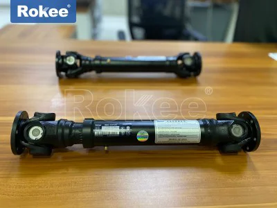
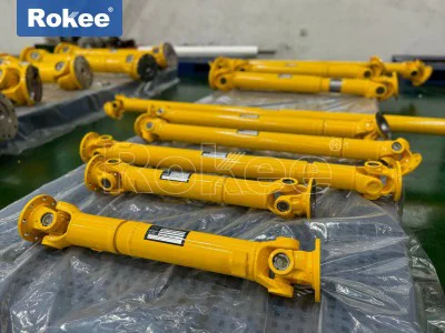
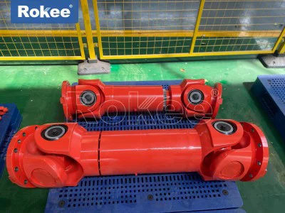
The cross axis universal coupling consists of two fork joints (universal coupling forks), a cross axis, and needle roller bearings.
Core Principle
Power transmission path: The driving shaft drives the cross shaft to rotate through the universal coupling fork, and the other end of the cross shaft drives the driven shaft universal coupling fork to rotate.
Angle compensation capability: The four necks of the cross shaft are connected to two universal coupling forks through needle roller bearings, allowing power transmission between the two shafts within a range of 5 ° -45 ° angles.
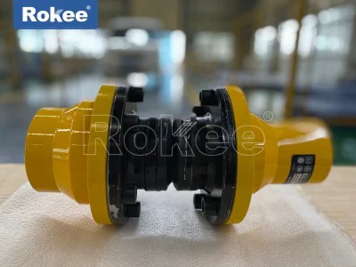
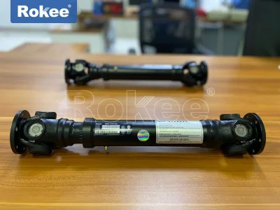
Double cross shaft couplings are commonly used in industry to counteract speed fluctuations and ensure consistent input/output shaft speeds through specific installation methods.
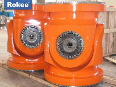
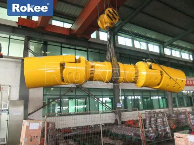
The SWC type adopts an integral fork head to enhance rigidity and is suitable for heavy-duty scenarios with a torque of up to 10000KN · m; SWP type split fork is easy to maintain and is commonly used in metallurgical equipment.
Typical applications
Automotive industry: Connecting the transmission and drive axle to adapt to suspension motion during driving.
Metallurgical machinery: The main drive shaft of the rolling mill compensates for the axis deviation caused by the lifting of the rolling mill rolls.
Construction machinery: The slewing mechanism of the crane transmits power to the walking device.
The cross axis universal coupling achieves non collinear shaft power transmission through a unique hinge structure, and its dual design solves the problem of speed fluctuations. The advancement of materials and bearing technology further expands its application boundaries in heavy-duty and high-speed fields.
In the realm of mechanical power transmission, the cross axis universal coupling stands as a fundamental and indispensable component, engineered to address the longstanding challenge of transferring rotational torque and motion between two shafts that are not collinear. Unlike rigid couplings that demand perfect axial alignment between driving and driven shafts, this specialized mechanical assembly leverages a unique articulated structure to accommodate angular misalignments, making it a cornerstone in countless mechanical systems where shaft positioning is constrained by design, installation tolerances, or operational movement. To fully grasp its functionality, one must dissect its core structural composition, trace the step-by-step path of power transmission, analyze the dynamic kinematic characteristics that define its performance, and explore the practical adaptations that mitigate inherent operational limitations, all of which collectively shape its working principle and real-world utility.
At its most basic level, the cross axis universal coupling is constructed around a minimal yet highly efficient set of core components, each engineered to perform a specific role in enabling flexible torque transmission. The primary elements include two fork-shaped yokes, a central cross shaft (commonly referred to as a cross journal or spider), and precision bearing assemblies that facilitate smooth articulation between the yokes and the cross shaft. Each yoke is rigidly affixed to one of the two shafts being coupled—one attached to the driving input shaft, the other to the driven output shaft—with a U-shaped fork end designed to cradle the corresponding ends of the cross shaft. The cross shaft itself features four perpendicular journal arms, arranged in a symmetrical cross formation, with two arms aligned to engage with the driving yoke and the remaining two oriented at a 90-degree angle to connect with the driven yoke. This perpendicular alignment is non-negotiable, as it forms the pivotal hinge mechanism that allows the two yokes to move independently in separate rotational planes while maintaining a continuous mechanical link. The bearing assemblies, typically needle roller bearings for high-load, low-friction performance, are mounted securely on each journal of the cross shaft, serving to reduce rotational friction, support radial and axial loads generated during operation, and enable the cross shaft to pivot and rotate freely within the yokes without binding or excessive wear. Unlike complex transmission components with redundant parts, this streamlined structure ensures the coupling operates with minimal energy loss while maximizing flexibility for angular misalignment.
The fundamental working principle of the cross axis universal coupling revolves around the conversion and transfer of rotational motion through this articulated cross-joint mechanism, a process that remains consistent regardless of the scale or load capacity of the assembly. When torque is applied to the driving shaft, the rotational force is transferred directly to the attached driving yoke, which begins to rotate around the central axis of the input shaft. As the driving yoke rotates, it exerts a mechanical force on the two engaged journals of the cross shaft via the bearing interfaces, causing the cross shaft to rotate in tandem with the driving yoke. Crucially, because the cross shaft is mounted on perpendicular journals, its rotation is not confined to a single plane; instead, it can pivot and swivel to accommodate the angular offset between the input and output shafts. This pivotal movement of the cross shaft then transmits the rotational motion to the second pair of journals, which in turn drive the driven yoke and the connected output shaft. In essence, the cross shaft acts as a movable intermediary, translating the rotational motion of the driving shaft into a multi-planar motion that can adapt to angular misalignments, then reconverting that motion back into pure rotational force for the driven shaft. This seamless transfer occurs even when the two shafts form a measurable angle—typically ranging from a few degrees up to approximately 45 degrees, depending on the design specifications—with the coupling maintaining full torque transmission capability throughout the rotational cycle. When the shafts are perfectly aligned collinearly, the coupling functions as a rigid connector, with the cross shaft rotating uniformly and no pivotal movement occurring, delivering a 1:1 direct drive ratio with zero speed variation.
A critical aspect of understanding the cross axis universal coupling’s working principle is recognizing the kinematic behavior that emerges when the coupled shafts operate at an angular misalignment, a characteristic that distinguishes it from constant-velocity couplings. In a single cross axis universal coupling, while torque is reliably transmitted across angled shafts, the angular velocity of the driven shaft does not remain constant throughout a full 360-degree rotation of the driving shaft, even when the input shaft rotates at a steady, uniform speed. This periodic fluctuation in output angular velocity stems from the geometric relationship between the cross shaft, the yokes, and the angled shaft axes. As the driving shaft completes one full rotation, the driven shaft experiences a cyclical pattern of acceleration and deceleration, with the magnitude of this speed variation directly proportional to the angle of misalignment between the two shafts. For instance, at small misalignment angles, the velocity fluctuation is minimal and often negligible in low-sensitivity applications; as the angle increases, the fluctuation becomes more pronounced, leading to potential vibration, dynamic stress on connected components, and uneven power delivery if left unaddressed. This non-uniform rotational output is an inherent trait of the single universal joint, rooted in its fundamental mechanical geometry, and it is essential to account for this behavior when designing systems to ensure operational stability and longevity.
To overcome the limitation of angular velocity fluctuation in single cross axis universal couplings, engineers have refined the working principle through the implementation of dual coupling configurations, also known as double Cardan arrangements, which restore uniform rotational speed between input and output shafts while retaining full angular misalignment compensation. This adapted setup consists of two separate cross axis universal couplings linked by an intermediate shaft, with precise phasing between the two joints to cancel out the velocity variations generated by each individual coupling. The key to this correction lies in aligning the two yokes of the intermediate shaft at a 90-degree phase shift relative to one another, and ensuring that the angle between the input shaft and the intermediate shaft is equal to the angle between the intermediate shaft and the output shaft. Under these conditions, the non-uniform velocity output of the first coupling is precisely counterbalanced by the opposing velocity fluctuation of the second coupling, resulting in a constant angular velocity for the final output shaft that matches the steady speed of the input shaft. This dual coupling design does not alter the core power transmission principle of the cross axis universal joint but rather optimizes its kinematic performance, making it suitable for high-precision applications where uniform rotation, minimal vibration, and smooth torque delivery are critical. Even in this dual configuration, the fundamental role of the cross shaft as the pivotal torque transfer element remains unchanged, reinforcing the primacy of the cross-axis articulation principle in flexible shaft coupling.
Beyond kinematics and torque transmission, the working principle of the cross axis universal coupling also encompasses its load-bearing capabilities and mechanical resilience, which are integral to its functional reliability across diverse operating conditions. The symmetrical design of the cross shaft distributes applied torque evenly across all four journal arms, preventing localized stress concentrations that could lead to component failure under heavy loads. The needle roller bearing assemblies, with their high contact area and low friction coefficient, enable the coupling to handle substantial radial and thrust loads while sustaining smooth articulation, even in high-speed rotational environments. Additionally, the robust mechanical linkage between the yokes and cross shaft ensures that torque is transferred directly without slippage, a key advantage over friction-based transmission devices. The coupling’s ability to accommodate not only static angular misalignments from initial installation but also dynamic misalignments that arise during operation—such as those caused by thermal expansion, mechanical wear, or structural deflection—further enhances its versatility. This adaptability is a core extension of its working principle, as the articulated cross-joint design inherently absorbs minor shifts in shaft position without compromising power transmission, reducing strain on adjacent components like bearings, gears, and shaft housings.
Practical operational considerations further illuminate the nuanced working principle of the cross axis universal coupling, particularly regarding lubrication, wear characteristics, and application-specific performance. Proper lubrication is vital to preserving the coupling’s functionality, as it reduces friction between the cross shaft journals and bearings, dissipates heat generated during high-speed rotation, and prevents premature wear and corrosion. The internal lubrication pathways integrated into most cross shaft designs ensure that lubricant reaches all critical contact surfaces, maintaining consistent performance over extended service life. Wear patterns within the coupling also reflect its core working principle: bearing surfaces and cross shaft journals experience gradual wear due to continuous articulation and load stress, which can increase backlash and reduce misalignment tolerance over time, highlighting the need for routine inspection and maintenance. Despite these considerations, the coupling’s simple, robust construction minimizes failure points, making it highly durable even in harsh operating environments such as industrial machinery, automotive drivetrains, agricultural equipment, and marine propulsion systems. In each of these applications, the core principle of cross-axis articulated torque transfer remains unchanged, with the coupling adapting to specific load, speed, and misalignment requirements through minor design modifications to component dimensions, material strength, and bearing specifications.
The widespread adoption of the cross axis universal coupling across countless mechanical systems is a direct testament to the efficiency and versatility of its underlying working principle. It fills a critical niche in power transmission by solving the fundamental problem of connecting non-collinear shafts, a challenge that rigid couplings cannot address and that more complex constant-velocity couplings solve at a higher cost and with greater design complexity. From heavy-duty industrial machinery that requires reliable torque transfer across significant angular offsets to precision automotive components that demand smooth, vibration-free rotation, the cross axis universal coupling delivers consistent performance by leveraging its simple yet ingenious articulated structure. Its design prioritizes functionality, durability, and adaptability, with every component and mechanical interaction serving the core goal of transferring rotational motion and torque efficiently across angled shafts. Unlike specialized transmission components tailored for narrow applications, the cross axis universal coupling’s working principle is universally applicable, making it a timeless and essential element in mechanical engineering design.
In summary, the working principle of the cross axis universal coupling is defined by its articulated cross-joint mechanism, which uses a centrally pivoted cross shaft to bridge two angled yokes attached to driving and driven shafts, enabling flexible torque transmission while accommodating angular misalignments. The core functionality relies on the perpendicular alignment of the cross shaft journals, which allow multi-planar pivotal movement to translate rotational motion across non-collinear shafts, with bearing assemblies reducing friction and supporting operational loads. While single couplings exhibit inherent angular velocity fluctuations under misaligned conditions, dual coupling configurations refine this principle to deliver constant-velocity output, expanding the coupling’s applicability to high-precision systems. Complemented by robust load distribution, dynamic misalignment compensation, and durable mechanical design, the cross axis universal coupling stands as a paradigm of efficient mechanical engineering, transforming a basic articulated structure into a versatile solution for one of the most common challenges in power transmission. Its enduring relevance stems from the elegance and reliability of its working principle, which balances simplicity, performance, and adaptability to meet the diverse needs of modern mechanical systems.
-
![Agricultural Cardan Shaft]()
Agricultural Cardan Shaft
-
![Material Selection Points Of Cardan Driveshaft For Sandwich Panel Production Equipment]()
Material Selection Points Of Cardan Driveshaft For Sandwich Panel Production Equipment
-
![Performance Test Method Of Cardan Driveshaft For PIR Sandwich Panel Production Equipment]()
Performance Test Method Of Cardan Driveshaft For PIR Sandwich Panel Production Equipment
-
![Synergy Efficiency Scheme Of Cardan Drive Shaft And Sandwich Panel Machinery]()
Synergy Efficiency Scheme Of Cardan Drive Shaft And Sandwich Panel Machinery
-
![Efficient Universal Coupling Helps Mineral Wool Sandwich Panel Production Line Reduce Cost And Increase Efficiency]()
Efficient Universal Coupling Helps Mineral Wool Sandwich Panel Production Line Reduce Cost And Increase Efficiency
-
![Integrated Application Of Cardan Shaft Coupling And PU Sandwich Panel Line]()
Integrated Application Of Cardan Shaft Coupling And PU Sandwich Panel Line
-
![Dynamic Performance Test And Analysis Of Universal Shaft Coupling In PIR Sandwich Panel Production Line]()
Dynamic Performance Test And Analysis Of Universal Shaft Coupling In PIR Sandwich Panel Production Line
-
![Special Cardan Shaft For PU Sandwich Panel Machine With Stronger Adaptability]()
Special Cardan Shaft For PU Sandwich Panel Machine With Stronger Adaptability